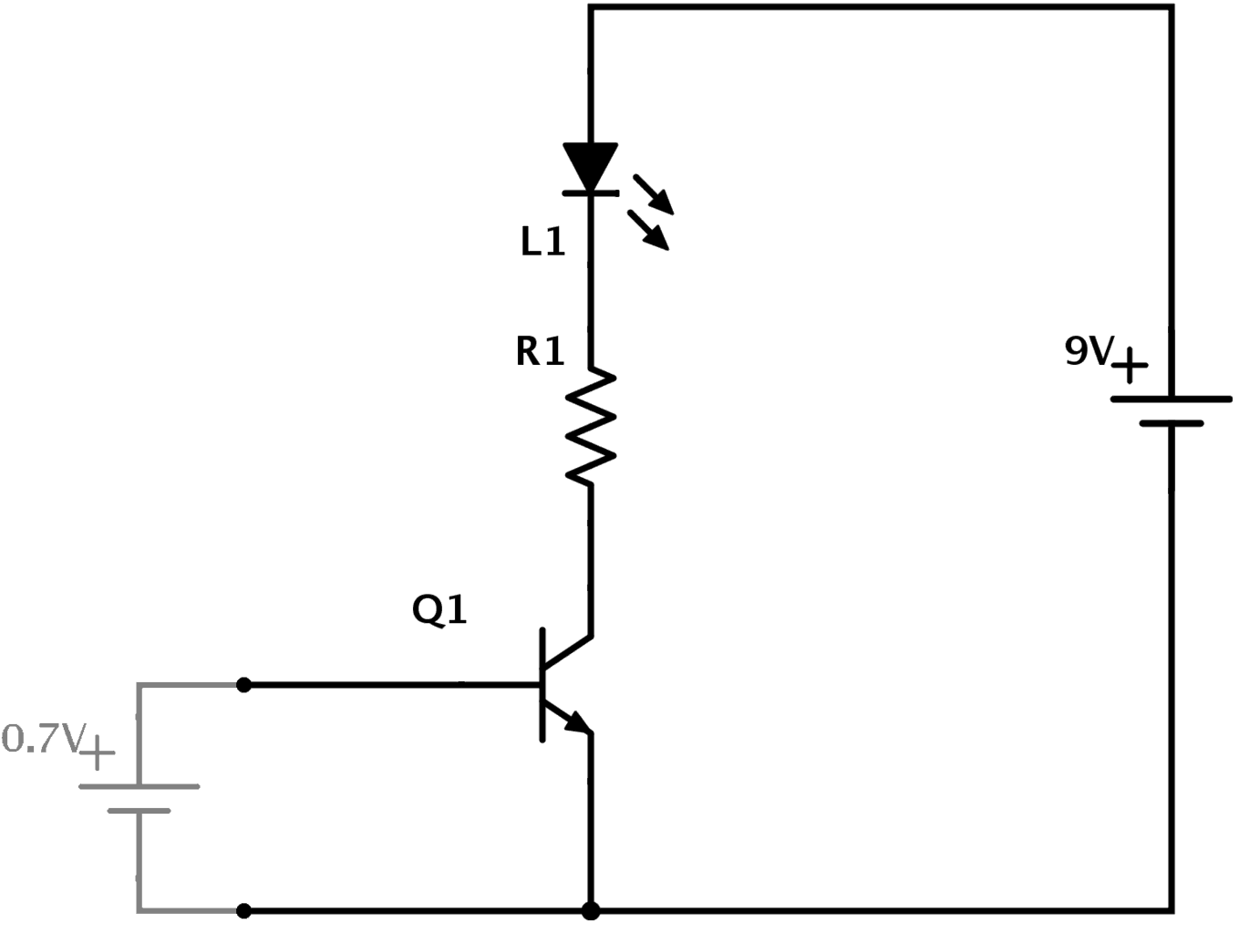

The current flowing by the remaining electrons is known as the collector current I C. Most of the electrons pass the depletion region of a collector-base junction and pass through the collector region. Typically, it is 2-5% of the total emitter current. Transistor Level Implementation of CMOS Combinational Logic Circuits 1 (c) show the schematic symbols for p- and n-channel MOSFET transistors. The base current is very small compared to the emitter current. When using the bipolar transistor as a switch they must be either fully-OFF or fully-ON. If Q1 is on, then C1s left plate (on the schematic) is connected to about 0V. Then to summarise when using a Transistor as a Switch the following conditions apply: Transistor switches can be used to switch and control lamps, relays or even motors. Hence, most of the electrons will pass the base region and few of them will recombine with the holes.īecause of the recombination, the current will flow through the circuit and this current is known as base current I B. Transistor switches are critical circuit-building blocks theyre used to.

So, it has a few holes to recombine with the electrons. But the base region is very thin and lightly doped. These electrons move further to the base. This current is known as emitter current I E. And because of electrons, the current will start flowing the emitter-base junction. An Integrated Circuit (IC) is usually shown as a rectangular box with pins. The schematic symbols for these types are shown below: Transistor symbols. Therefore, electrons start flowing from N-type emitter to a P-type base. The most common transistor types are the Bipolar Junction Transistor (BJT), Darlington Transistor, and the Field Effect Transistor (FET). NPN transistors have the emitter connected to the negative supply rail and the current flows out of the Transistor into the negative supply rtail and you. One LED (Light Emitting Diode) to check the output. By using a synchronous rectifier to measure the in-phase component of the capacitor impedance. The design is unusual in that it uses 10kHz, instead of the more usual 100kHz. They mainly perform two functions: switching and amplification. Before I designed the 5 Transistor ESR meter, I designed and built an ESR meter using a digital panel meter. Their ease of use and simple working principle is what makes them popular among electronic designers. Transistors are one of the most commonly used elements in electronic circuits. (You can also use PNP transistor if available) Two 10K resistors & one 4-5K resistor. Transistors 101: A Detailed Introduction to Using Transistors. In N-type emitter, the majority charge carrier is electrons. The list of components required to build an AND gate using an NPN transistor are listed as follows: Two NPN transistors. The depletion region of the emitter-base region is thin compared to the depletion region of the collector-base junction (Note that the depletion region is a region where no mobile charge carriers are present and it behaves like a barrier that opposes the flow of the current).


 0 kommentar(er)
